
Features

The engineering, in detail.

What FoundaTrix Studio computes for every rigid foundation, the standards it follows, and where it stops. Every check names the provision it comes from, and the built-in manual explains each method so you can verify it yourself.

Foundation types · Free

One method for every rigid foundation.

A spread footing is the simplest case of what the program does, not the limit of it. Any foundation that acts as a rigid body, of any outline and carrying any number of pedestals, takes the same exact path through the analysis and the design.

  • Spread footings

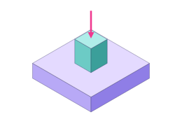
    One pedestal on one footing: the column or equipment base, in any outline.

  • Combined footings

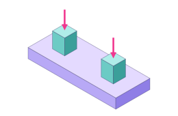
    Two or more pedestals sharing one footing, each with its own loads, cage and anchor rods.

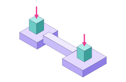
  • Strapped footings

    Two footings joined by a strap beam and analysed as one rigid body; the strap designed as a grade beam.

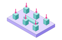
  • Mat foundations

    One mat under many pedestals and plinths, from an equipment skid to a substation pad.

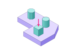
  • Any outline

    Rectangles, circles, octagons and irregular polygons, with pedestals of any shape placed anywhere on them.

The one condition: the foundation acts as a rigid body. It must be stiff enough for the bearing pressure to vary linearly across the base: the classical assumption the whole method rests on. Where part of the base lifts, the soil carries nothing there and the program finds the part still bearing.

Analysis · Free

Bearing, overturning and sliding, for any outline.

Every foundation, from a single footing to a mat, is analysed on its own soil under every load combination. The foundation is rigid and the soil cannot pull: where a linear distribution would go into tension, the base lifts and the program finds the part still bearing.

Bearing pressure

Free

Solved exactly under partial uplift

  • Rectangular, circular, octagonal and irregular bases take the same path; none is approximated as something simpler
  • Where the base lifts, the neutral axis is solved so the pressure resultant sits exactly where the load acts
  • Partial contact and net uplift reported for every combination, with the share of the base still bearing
  • The net allowable from your geotechnical report converted to gross with each footing's own depth
  • A short-term increase for wind and seismic rows, when you specify one

Stability

Free

Overturning and sliding that mean something for any shape

  • Overturning measured geometrically, from the plan centroid through the resultant to where it leaves the base
  • Sliding as base friction plus passive resistance, the passive credit off unless you supply a coefficient
  • ASCE 7-22 prescribes no factor of safety: an ordinary footing is held to a ratio of one unless you state a target
  • Wizard-built petrochemical foundations take the targets their governing guides ask for

Load combinations

Free

ASCE 7-22 Chapter 2, traced to the line of the standard

  • Strength design (Section 2.3) and allowable stress (Section 2.4), the seismic combinations of Sections 2.3.6 and 2.4.5 included
  • Every printed combination that offers a choice is expanded into one case per choice, named after the line and the alternative it took
  • The vertical seismic effect, 0.2 SDSD, folded into the seismic rows; the soil-interface exception of Section 12.4.2.2 offered, and off by default
  • Lateral loads that act one way or either way, and the two horizontal directions combined as the standard permits
  • Or supply your own factored combinations, pasted straight from a frame analysis

Concrete design · Free

ACI 318-19, worked over every strength combination.

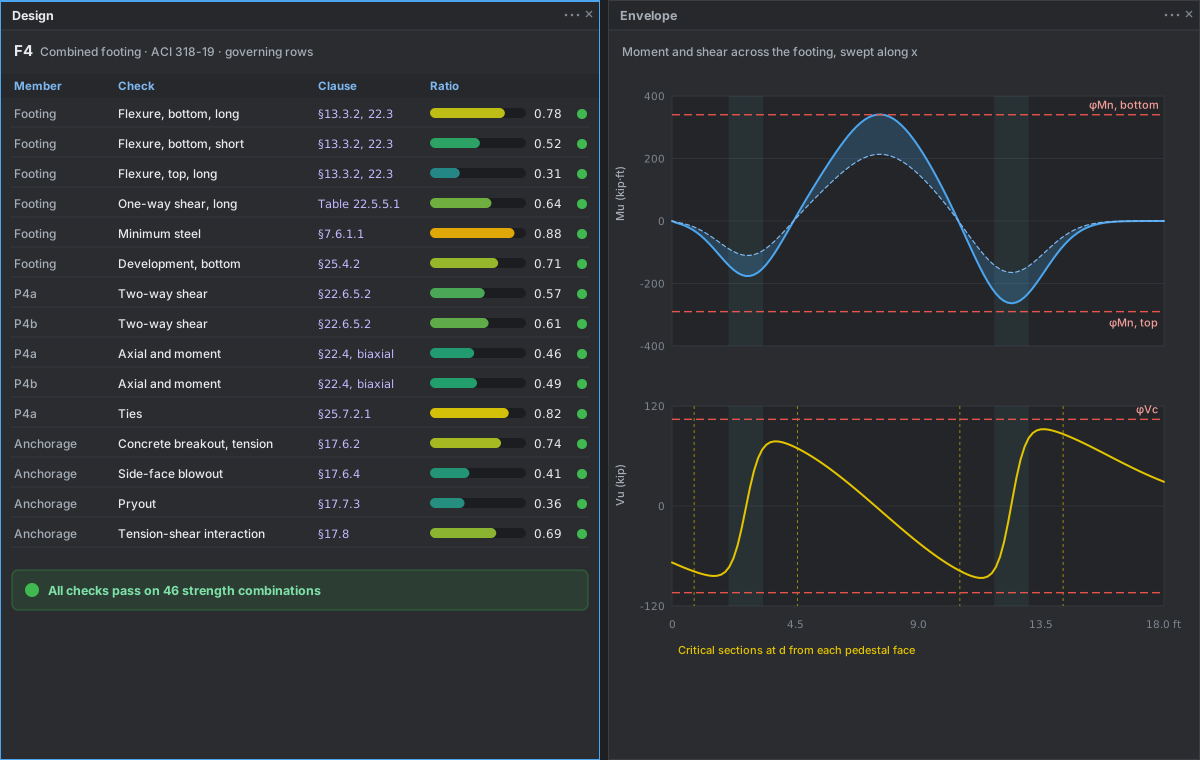
The design runs in the same pass as the analysis. The strength cases design the concrete; the allowable-stress cases judge the soil. Every row of the design says which clause it checks.

  • Footings and mats: two-way shear on a critical section at d/2 from each pedestal, merged where sections overlap and trimmed at an edge, with the transferred moment's eccentric shear
  • One-way shear and flexure from a section swept across the footing along the bar direction you choose; Table 22.5.5.1 with the size effect
  • Four independent mats sized and the bars picked, with minimum steel, development and standard hooks that must fit
  • Pedestals: axial force and biaxial moment on a full strength surface, plain or reinforced, with ties and seismic detailing
  • Strap footings: two footings and their strap as one rigid body, the strap a grade beam, by strut-and-tie where it is deep
Studio · Design
The Design pane listing each check with its ratio and ACI 318-19 clause, beside the swept shear and moment envelope.

Anchor rods · Free

Cast-in anchorage to ACI 318-19 Chapter 17.

Two bodies of work sit under one heading and both bind: the dimensions that keep the concrete from splitting, and the strength of every failure mode the chapter gives an equation for.

Dimensions

Spacing, edges and embedment

Minimum spacing and edge distance from Table 17.9.2(a), measured along the chord between rods, and the embedment and gauge length the ASCE anchorage guide and PIP STE05121 ask for.

Strength

Every mode, and their interaction

Steel in tension and shear, concrete breakout, pullout, side-face blowout and pryout, and the tension-shear interaction; Section 17.10's seismic requirements on the seismic rows.

Hardware

The rods you would specify

Standard rod sizes with their nuts, washers and threads read from the standards, grouted base plates, anchor plates, and anchor reinforcement designed when breakout governs.

Why post-installed anchors are left out

Chapter 17 says the pullout strength of expansion, undercut, screw and adhesive anchors may not be calculated at all: it comes from a product evaluation report. A number computed for them here would be a number the standard forbids, so the program does not offer one.

The Studio · Free

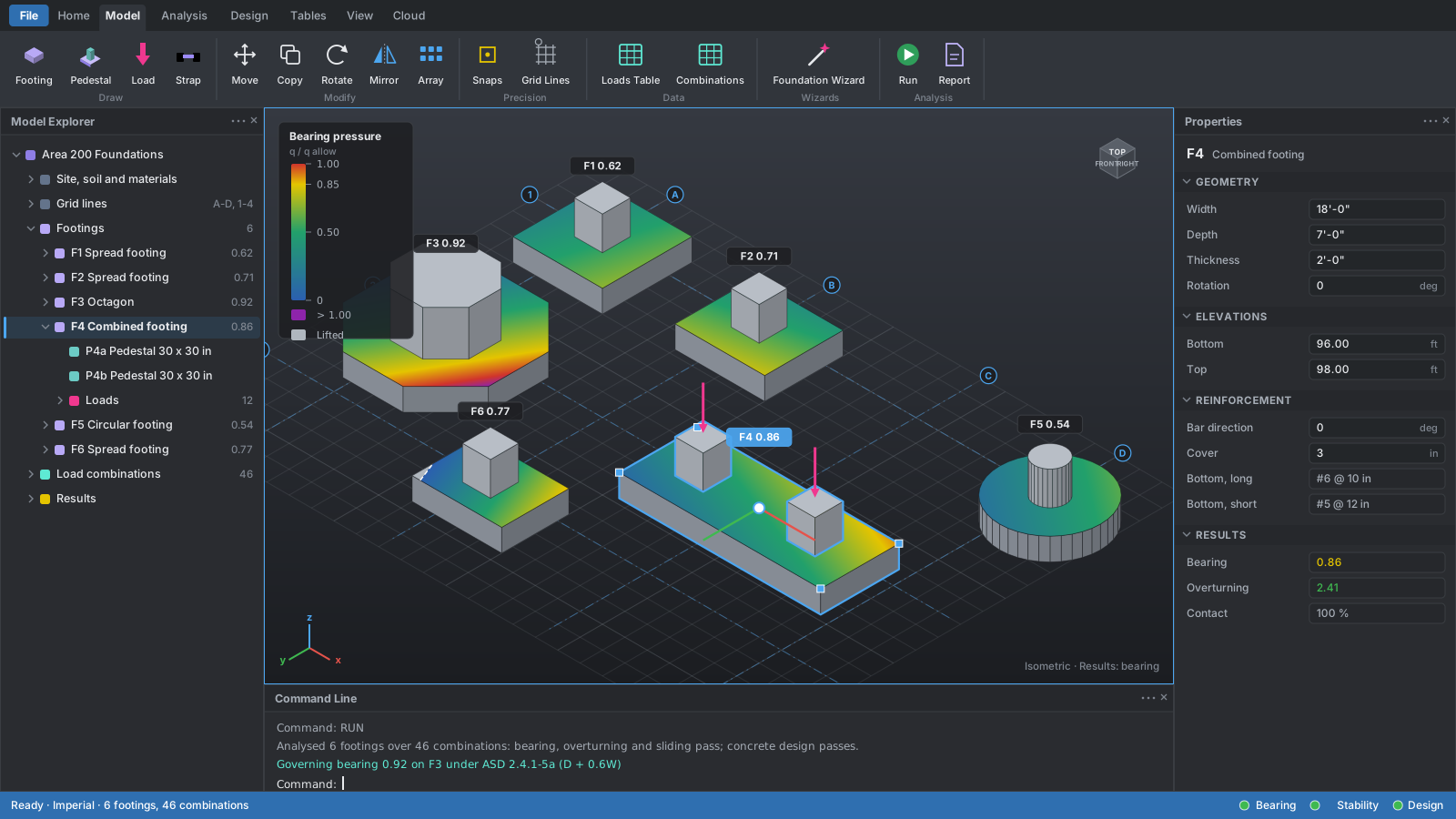
A 3D modelling environment that works like drafting.

A project is a three-dimensional model of a site: footings at positions on the site, each with its pedestals and loads, over one soil and one set of materials. Commands are clicked on the ribbon or typed, and answered with a click or a value.

  • Absolute, relative and polar coordinates; snaps to ends, midpoints, centres, intersections, perpendiculars and the grid; ortho, polar tracking and axis locks; set-out grid lines
  • FOOTING, PEDESTAL, LOAD, MOVE, COPY, ROTATE, ARRAY, MIRROR, MEASURE and ERASE, each one undo step
  • Hide, isolate and unhide; named views; pictures of the view with labels and dimensions
  • Model Explorer, Properties and Command Line in panes you can dock, float, pin or move
  • The model checked as you build it, every problem with a code, a sentence and its object
  • Unlimited undo that survives a save, and Reset to the last save in one step
FoundaTrix Studio — Sample Project
The Studio workspace with the Model Explorer, a 3D view of a site's footings coloured by bearing pressure, and the Properties pane.

Tables & data · Free

Your data, in the formats you already use.

Tables beside the model

Footings, pedestals, loads and combinations as spreadsheet-style tables that stay in step with the 3D model.

Clipboard in and out

Copy with headers, edit in your spreadsheet, paste back; comma, semicolon and tab-separated text all land.

Formulas and feet-inches

Type = and a formula in any number field, and Imperial lengths as feet and inches.

Plain-text projects

One .rfnd file per project, readable, diffable and easy to send to a reviewer.

Wizards · Premium

Five families of equipment, each to its governing practice.

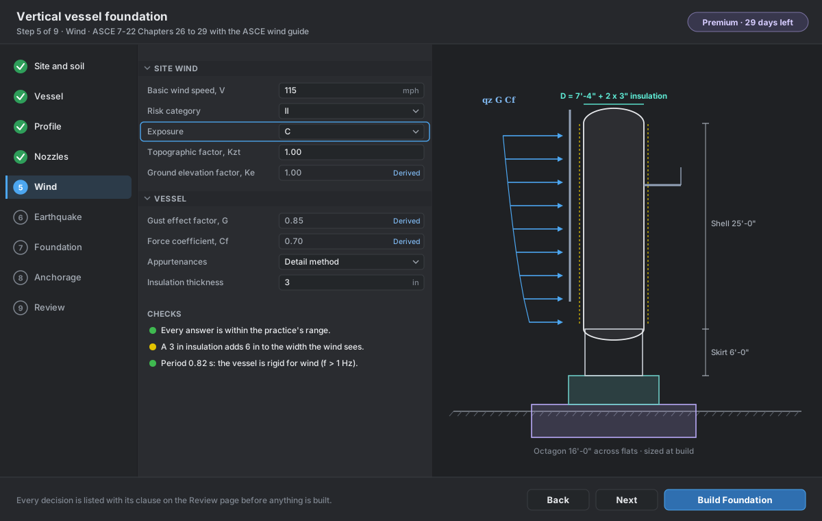
A wizard asks about the equipment and its site, checks every answer as you type, and builds the complete foundation once, when you say Build: loads, combinations, trial sizes and anchorage, with each decision recorded beside its clause.

Vertical Vessel Wizard — Wind
The vertical vessel wizard: steps, questions, a to-scale drawing of the vessel and the page's checks.

Petrochemical foundations follow the ASCE guides.

For vessels, exchangers and pipe supports, the three ASCE petrochemical guides for wind, seismic and anchorage govern together with ASCE 7-22, and the PIP practices supplement them where the guides are silent. Substation equipment follows ASCE MOP 113 and the IEEE standards instead.

  • Each wizard lists every decision it made, with its clause, before it builds anything
  • What it builds is an ordinary foundation, open to every edit, analysis and design
  • A size you state is built as stated; a conflict is said, never silently resized
Vertical vessels

Towers, drums and reactors

  • Uniform or stepped shells, skirts, and where the contents sit
  • Nozzles with their loads carried to the base; pipes, platforms and insulation
  • The period over the skirt and shell; the test weight's ceiling
  • Octagonal foundations checked on their diagonal; pedestal ties around the rods
  • Energy-balance stability for existing facilities

PIP STE03350 · ASCE 7-22 · ASCE wind, seismic and anchorage guides
Horizontal vessels & exchangers

Units and stacked pairs on two saddles

  • Shell-and-tube exchangers and horizontal vessels, single or stacked
  • Thermal forces at the sliding saddle and bundle pull
  • Weights from the practice's figures when none is stated
  • Anchor rods in a row, designed to Chapter 17
  • Two spread footings, one combined slab, or a strap

PIP STE03360 · ASCE 7-22 · ASCE petrochemical guides

Substation equipment

Transformers, breakers, switches, bus supports

  • A structure and the equipment types placed on it, defined once and reused
  • Every insulator and bushing checked for gravity, wind, fault and earthquake, tilted ones included
  • Transformer oil containment pits, three ways, with plinths
  • The stand analysed as a frame for its foundation's reactions

ASCE MOP 113 · MOP 161 · IEEE 693, 605, 980 · ASCE 7-22

Pipe supports & racks

T-supports and pipe rack bents

  • Pipes, conduits, cable trays and walkways, with friction and anchor forces
  • Reactions from your piping stress analysis, case by case
  • Wind on banks of lines; snow, ice, walkway live load and thermal effects
  • Several bents from one, each with its own footing

PIP STC01015 · ASCE 7-22 · ASCE petrochemical guides

Every wizard

Loads you can see

  • Any load set drawn on the model, force for force as the analysis receives it
  • The drawing follows your cursor through the questions
  • Notes carried to the report and the command line

Steel design · Premium

AISC 360-22 by the direct analysis method.

Substation stands, T-supports and pipe racks are analysed whole, second order, under every strength combination, then each member is checked by LRFD at every station along it.

  • P-Δ and P-δ with the specification's stiffness reductions and notional loads; tension-only bracing; instability reported, never hidden
  • Members to Chapters D to H by family, including torsion of open sections; Cb worked from the structure
  • Base plates to AISC Design Guide 1, third edition, with Design Guide 10 for rods beyond the column
  • The column's fillet weld to Section J2.4; deflections to the governing practice
  • Name a group such as W12 and get the lightest section that passes, from the AISC shapes database
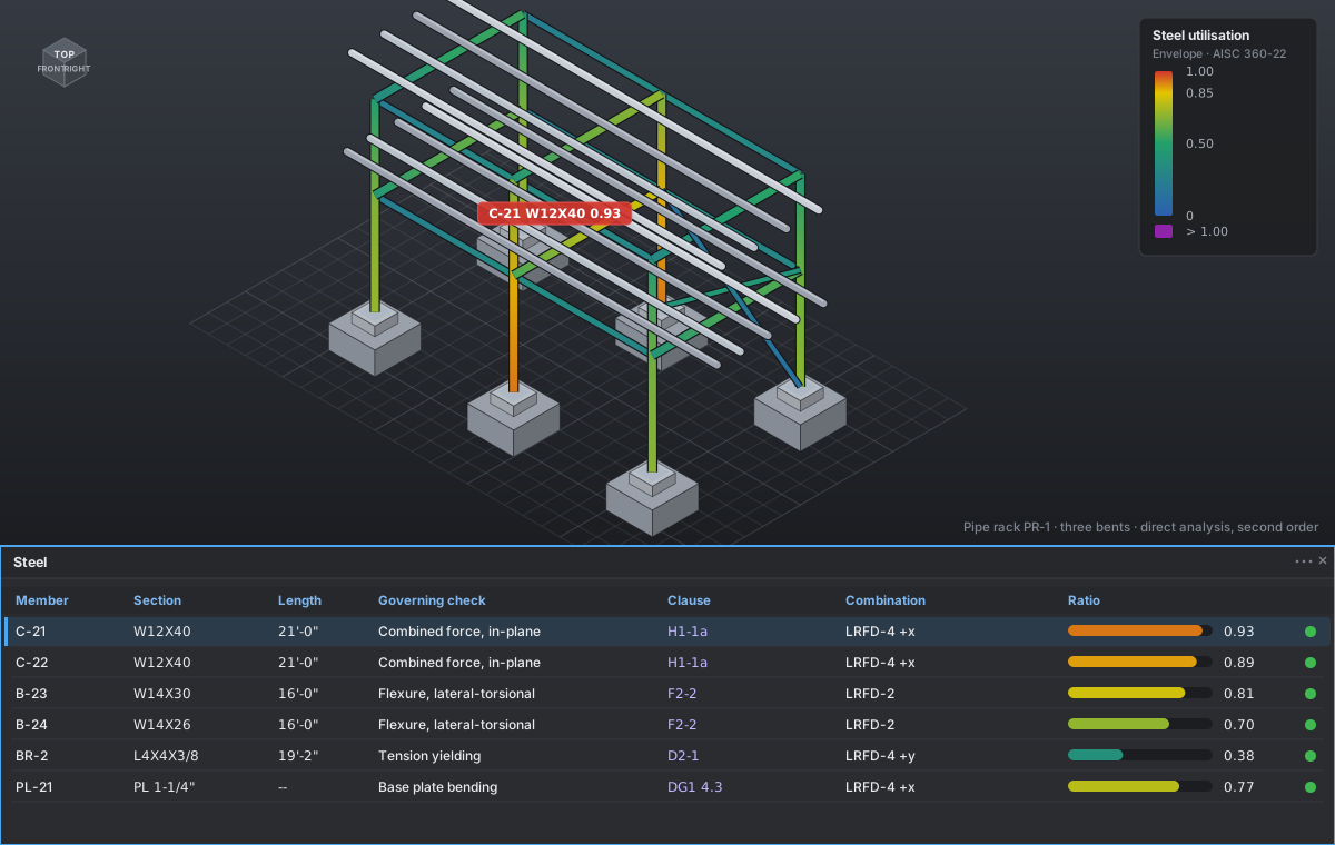
  • The model coloured along each member by utilisation, for the envelope or one combination
Studio · Steel
A pipe rack coloured member by member by its AISC 360-22 utilisation, with the Steel pane.

Calculation report · Premium

A calculation package a reviewer can follow.

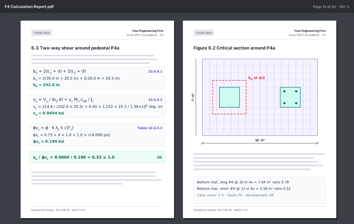
A typeset PDF in which every derivation is printed twice: once symbolically, and once with your numbers and units substituted, each beside the clause it comes from.

  • Your firm's name and logo on the cover and the page headers; your paper size
  • Dimensioned figures of the footing, the pedestals, the reinforcement and the anchorage
  • The basis of design, the register of assumptions and the references, always included
  • Written only from a current analysis, and marked NOT A DESIGN where that applies
Calculation Report
Two pages of the calculation report: a derivation symbolic then substituted with its clause, and a dimensioned figure.

IFC & Revit export · Premium

Coordinate the foundation with everyone else's model.

The physical model is written from the document, never from the screen: IFC 4.3 for any openBIM tool, or a Revit exchange file that the included Ramisoft Revit add-in builds as native, editable Revit elements.

  • Footings, pedestals, straps and pits, with property sets and quantities
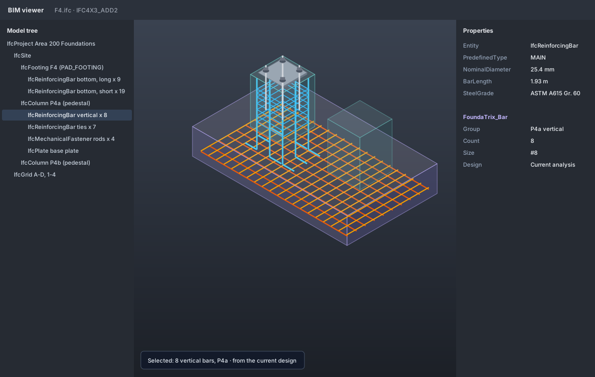
  • Reinforcement from the current design as real bars; anchor rods with nuts, washers and drilled base plates
  • SI units at the boundary and stable identities, so exporting again updates the model
  • One add-in for Revit 2025, 2026 and 2027, run and tested in Revit 2026
BIM viewer — F4.ifc
An exported foundation in a BIM viewer, with reinforcement, anchor rods and a drilled base plate.

Cloud · Free account

Jobs and designs that follow you, when you sign in.

Signing in is optional and free with an email address. One Ramisoft account signs in to FoundaTrix Studio and RPile alike, and a job can hold designs from both.

Jobs and designs

A job per site, holding its designs; open them on any computer you sign in on.

Version history

Every save is a version, with your comment beside it; saved versions are kept for six months.

Recycle bin

Deleted jobs and designs wait thirty days, where you can restore them.

Your organization

Share a job with the organization you belong to; whoever is editing a design is shown to the others.

Searchable descriptions

Describe a design in a sentence and find it later by meaning, not only by name.

Premium

Job map and address lookup

Your jobs as pins on a map; place a new job by its address or on the map.

Limits

What it does not do, said plainly.

So you know what still needs doing elsewhere. The user's manual lists every assumption and every limit.

The soil response is not modelled

No subgrade modulus, settlement or bearing capacity from soil strength parameters. The allowable bearing pressure is your geotechnical engineer's, taken as given.

Post-installed anchors

Deliberately absent: their strengths come from product evaluation reports, not from Chapter 17's equations.

Lateral earth pressure

Not a load case. Passive resistance enters sliding only when you supply a coefficient.

References

The documents behind the checks.

  1. ACI Committee 318 (2019). ACI CODE-318-19, Building Code Requirements for Structural Concrete and Commentary. American Concrete Institute.
  2. ASCE/SEI 7-22 (2022). Minimum Design Loads and Associated Criteria for Buildings and Other Structures. American Society of Civil Engineers.
  3. ANSI/AISC 360-22 (2022). Specification for Structural Steel Buildings. American Institute of Steel Construction.
  4. AISC Design Guide 1, third edition (2024). Base Connection Design for Steel Structures. AISC Design Guide 10, second edition (2020), for rods beyond the column.
  5. ASCE (2020). Wind Load Design for Petrochemical and Other Industrial Facilities.
  6. ASCE, third edition. Seismic Evaluation and Design of Petrochemical and Other Industrial Facilities.
  7. ASCE (2022), second edition. Anchorage Design for Petrochemical Facilities.
  8. ASCE Manual of Practice 113 (2023), substation structure design, and Manual of Practice 161.
  9. IEEE 693-2018, seismic design of substations; IEEE 605-2023, bus design in air-insulated substations; IEEE 980-2021, containment and control of oil spills in substations.
  10. Process Industry Practices: STC01015, structural design criteria; STE03350, vertical vessel foundations; STE03360, heat exchanger and horizontal vessel foundations; STE05121, anchor bolts.
  11. buildingSMART International. IFC 4.3 ADD2 (ISO 16739-1:2024).

See it on your next foundation.

Download FoundaTrix Studio free, with no account, and run a foundation you already know the answer to. Then sign in to try the premium tools for 30 days.